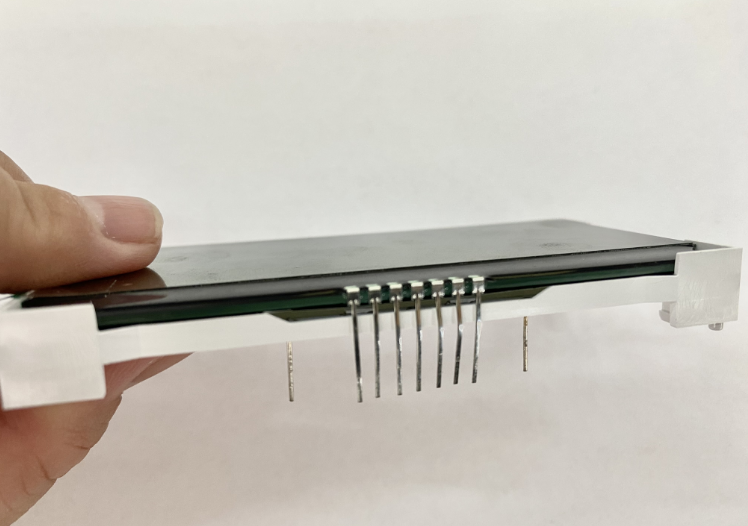
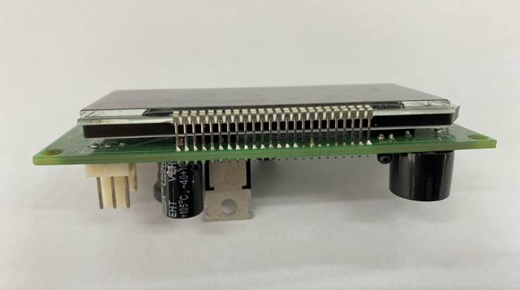
We all know that the display screen is a passive electronic accessory. It needs to be driven by a driver board with instructions to work. Therefore, a bridge is needed to transmit signals between the driver board with instructions and the LCD screen. This bridge is commonly found in pin header connectors and FPC flexible connectors. This chapter will compare these two connector methods in detail for COG displays, so that customers can choose the most suitable solution.
Metal pin header connection
Pin headers are a basic electronic component used for circuit connection and are usually found on circuit boards of electronic devices. They provide a path for electrical connection between electronic components and have a wide range of uses, such as module connection, signal transmission, and test point setting.
Connections between circuit modules:Pin headers are usually used to connect modules between circuit boards, such as providing an electrical interface between a main board and a daughter board, or an expansion board. This design allows for quick replacement and upgrade of modules, helping to improve the maintainability and scalability of the system.
Signal transmission:Pin headers provide a way to transmit multi-channel signals through pin arrangement, ensuring that electrical signals are effectively transmitted between different circuit boards. For example, pin headers are an ideal choice for connection occasions that require a large number of pins, such as display interface and storage device interface.
Circuit testing and debugging:During the circuit design and production process, pin headers are often used as test points. Electronic engineers can use the pin headers to insert test equipment to measure and monitor parameters such as voltage and current of a specific circuit, making it easier to debug and detect faults.
Modular design application:In the modular design of modern electronic devices, pin headers make the connection between functional modules more flexible. For example, on a computer motherboard, pin headers are used to connect different expansion cards and peripheral devices to achieve flexible hardware configuration.


advantage:
Diversity and flexibility: The pin headers have a variety of specifications and arrangements to meet different circuit design requirements.
Reliable connection: The metal pins ensure good conductivity and mechanical stability, suitable for a variety of environmental conditions.
shortcoming:
Space occupied: In high-density circuit board design, the pin header may occupy a large space, limiting the compactness of the circuit.
Easy to oxidize and wear: The metal part of the pin header may be oxidized and worn during long-term use, affecting the reliability of the connection.
High welding requirements: When connecting the pin header to the driver board, a welding process is required. This operation requires the welder to have certain skills and has very high requirements for welding temperature, welding time, etc. If one of the links is not up to standard, the contact point connected to the display end will expand and contract repeatedly, and this consequence will have a great impact on the transmission signal.
High yield rate and low cost: Based on the stringent requirements of welding technology, it is easy to damage and scrap the product, increase labor costs and the cost of waste. Therefore, although this is a very intuitive and simple connection method, when considering controlling the total cost, this method may not be the best solution.
Summary: As an important electronic component, pin headers play a key role in circuit connection and signal transmission. By properly selecting and using pin headers, the flexibility and reliability of circuit design can be effectively improved to meet the needs of different electronic devices. Understanding the characteristics and usage of pin headers can help electronic engineers better design, debug and maintain circuits.
Flexible FPC connection method:
For more details, please click on the link article:What are the advantages of flexible FPC connectors?
COG display, which connection method should I choose?
Now that we understand these two connection methods and their advantages and disadvantages, what is the most suitable connection method for COG displays?
As we all know, COG - Chip On Glass, refers to assembling the chip onto the LCD screen. This method makes the screen structure look simpler, small in size, and has good shock resistance. Therefore, COG is widely used. The PIN definition derived from COG contains a line with a signal, which affects which type of connector is used to lead out the signal.
Use metal pin connector: As described above, this method requires the use of welding to connect the display to the driver board. If the welding technique is not up to standard or the operation is wrong, the contact point on the LCD end will expand and contract repeatedly. Because these pins represent signal lines, if one of the metal PINs is damaged, it will cause the entire COG display to be abnormal, making repairs difficult.
Use flexible cable FPC connection: no welding is required, only a simple assembly process is required, avoiding the risks brought by metal PIN.
To sum up: If you have very good welding technology, you can use metal PIN needles between COG and its driver board, but the risk is high. Once a needle is welded wrong, the entire COG will not work. Using flexible FPC is the best choice for high-quality COG display products!
For more information, please contact us directly!


 Search


